FAQ - Frequently Asked Questions
Here you will find the answers to your most frequently asked questions.
Web Tension
How is web tension measured?
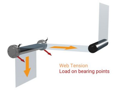
The web tension is measured indirectly via an idler roller over which the web is guided. The tension of the web creates a load on the roller. This load can be measured by two force sensors (load cells) on each side of the idler roller.
What is tension monitoring?
Web or strand tension monitoring is the measurement of the tensile stress on materials that are processed continuously from roll-to-roll. Such materials include plastic or metal foils, paper, labels, textiles, metal strips, composite materials, cables, wires, yarns, or fibers.
Since the web tension cannot be measured directly in the material, the occurring force in an idler roller or pulley is measured when the processed material is fed around. The web tension is proportional to the wrap angle of the material.
Web tension measurement is used in the production and processing of continuous materials. In other words, it is necessary to prevent materials from being damaged by excessive or insufficient web tension. Excessive web tension often means that the material is stretched or even breaks. In contrast, insufficient web tension can lead to wrinkles, for example.
A measuring point for web tension measurement consists of two force sensors, one at each end of an idler roller, and a measuring amplifier. The force sensors provide a measuring signal which is processed by the measuring amplifier and forwarded to the PLC or the higher-level control system. In the simplest case, the measuring amplifier calculates the average of the two measured values and transmits this as an analog signal (current or voltage signal). More complex measuring points can evaluate the two force values separately and thus detect, for example, uneven tension distribution across the web. Signal transmission can also be provided via fieldbus or ethernet.
What is the unit of web tension?
Web tension is nothing other than a tensile force. The SI unit for force is Newton N (metric), or Pound-force lbf (imperial). A typical unit, independent of the material width is N/m or lbf/in.
What is the torque of web tension?
Web tension and torque are linked by a mathematical formula. Torque = web tension x radius of a roll. If I want to keep the web tension constant, simple rules apply: If the diameter of the rewinder increases, I need increasing torque on the rewind shaft; if the diameter of the unwinder decreases, the torque of the unwind shaft decreases.
Force Sensors
What is a force sensor?
Force sensors are used to measure compression, force, strain and load. Many have internal strain gauges bonded to the metal structure which react to even the smallest deformation causing a change in resistance and giving feedback on these results. Force sensor is an alternative term, depending on the design and application they may also be called load cell, force transducer or force measuring bearing.
What are typical causes of measurement errors?
- Fixed and floating bearing installation of the measuring roller not implemented or implemented incorrectly
- Worn roller bearings, increased friction
- Contact between the measuring roller and other system components (antistatic device, pressure roller, cleaning brush, etc.)
- Inertia during rapid speed changes of the measuring roller
- Installation position and orientation of the force sensor not according to specifications
- Use of the correct mounting variant and mounting screws
- Compliance with the permissible torques for mounting screws
- Corrosion inside the force sensor due to leakage
- Electromagnetic interference on e.g. sensor cable
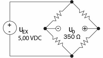
- Supply voltage 5.00 VDC at force sensor
- Negative output signal due to reversed signal or supply voltage wires.
If you can rule out these causes, please contact us.
What are the typical signals from force sensors and measuring amplifiers?
- The force sensor is supplied with a highly stable 5 V exciatation voltage from the measuring amplifier. This voltage must be 5.00 V
- The output signal of an unloaded force sensor is 0 mV. -1 to +1 mV is within the tolerance range.
- If the force sensor is loaded with the full nominal force, the output signal is 9 mV.
- If the output signal is negative under load, either the polarity of the supply voltage or the polarity of the signal lines must be reversed.
- The output signal of the force sensor is proportional to the load. This means that at half load (50% of the nominal force), half the output signal is present. This would be 4.5 mV.
- The output signal at the measuring amplifier is either a
voltage output (-10 to +10 V) or a
current output (0/4 to 20 mA) - If the voltage output from the measuring amplifier is negative, either the polarity of the supply voltage or the polarity of the signal lines must be reversed.
- If the current output of the measuring amplifier is always 0 or 4 mA, regardless of the force applied, the calibration must be repeated. If this does not help, either the polarity of the supply voltage or the polarity of the signal lines must be reversed.
- The output signal of the measuring amplifier is proportional to the force. This means that at half load (50% of the rated force), half the output signal is present. For the voltage output, this would be 5 V, for the current output either 10 mA (0 to 20 mA) or 12 mA (4 to 20 mA).
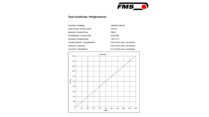
What is the sensitivity of a force sensor?
This value describes the dependence of the output signal on the excitation voltage. The sensitivity is usually specified in mV/V and is 1.8 mV/V as standard for FMS. This means that for every volt of excitation voltage, one millivolt is generated in the output signal: At 100% nominal force, this means:
5V x 1.8mV/V x 100% = 9mV output signal
At 50% nominal force:
5V x 1.8mV/V x 50% = 4.5mV output signal
What are ATEX applications?
This refers to areas of installation where explosions can occur. An explosion hazard can be caused, for example, by dust or flammable vapors. The exact definition and requirements for devices that may be used under such conditions are defined in Directive 2014/34/EU.
In addition to force sensors and measuring amplifiers, FMS offers an intrinsically safe barrier for precisely these applications. These are connected between the force sensor and the measuring amplifier and allow safe operation.

Repeatability and accuracy in web tension measurement
Accuracy – Is your measurement correct? How close is the measurement to the actual value?
Example: The web tension is 100 N, and 100 N is measured – this measurement is accurate.
Repeatability – Is your measurement consistent? How does the value change when I measure the same dimension several times in a row, or how large is the measurement variation?
Example: The web tension is 100 N. Five measurements are taken in each case:
1st measuring point: 99.5; 99.8; 100.1; 99.9; 100.2 N
2nd measuring point: 100.0; 99.9; 100.0; 100.1; 99.9 N
A lower measurement variation means higher repeatability.
Low accuracy can be improved through better calibration.
If repeatability is poor, it is impossible to tell whether the deviations are in the product or caused by variation in the measuring system.
Repeatability = consistency
Accuracy = correctness
Consistency is essential.
What is a Wheatstone full bridge?
At FMS, we only use the so-called full bridge with a nominal resistance of 350 Ω. This means that the resistance of the unloaded force sensor is 350 Ω between the output connections. Four resistors are connected in such a way that when deformation occurs, two resistors are compressed and two are elongated. This has the advantage that temperature fluctuations are compensated to a certain extent, as the corresponding length expansions compensate each other. In addition to the full bridge circuit, there are also quarter-bridge and half-bridge circuits.
What does the protection class indicate?
The protection class indicates the degree of protection against moisture, solid objects, or contact. At FMS, the protection class for force sensors and electronic housings (e.g., measuring amplifiers) is indicated by the IP code. IP is followed by two digits, the first of which stands for protection against objects and the second for protection against water.
First digit (protection against objects and contact):
0: No protection
1: Protection against solid objects > 50 mm (e.g., accidental contact with the hand)
2: Protection against solid objects > 12.5 mm (e.g., fingers)
3: Protection against solid objects > 2.5 mm (e.g., tools, wires)
4: Protection against solid objects > 1 mm (e.g., small tools, thin wires)
5: Dust-protected
6: Completely dust-tight
Second digit (water protection):
0: No protection
1: Protection against dripping water
2: Protection against falling spray water at an angle of up to 15°
3: Protection against falling spray water at an angle of up to 60°
4: Protection against splashing water from all directions
5: Protection against water jets (from any direction)
6: Protection against strong water jets (from any direction)
7: Protection against temporary immersion
8: Protection against permanent immersion
9K: Protection against high-pressure and steam jet cleaning
What is the difference between excitation voltage and supply voltage?
The term excitation voltage is usually used for force sensors whose strain gauges are connected to a highly stable power supply. Normally, the 5 V supply is provided by a measuring amplifier. The specifications here must be strictly observed. Excessive voltages cause the strain gauges to overheat, and unstable voltages result in inaccurate measurement results.
The measuring amplifier itself requires a supply voltage of 24 V. The possible voltage range here is 18 to 36 V.
EMC Electromagnetic compatibility
Electromagnetic fields can have a negative impact on the accuracy and function of measuring devices. For this reason, all our devices are tested for this so-called interference immunity and to ensure that they comply with the specified limits even when emitting electromagnetic fields. Both are specified in the EMC Directive 2014/30/EU.
Do all FMS force sensors have overload protection?
Yes, all force sensors have a mechanical stop to protect against permanent deformation or overload. The design of the stop is very individual for each series. However, the operating principle is always the same. At a load of approx. 10 to 30% above the specified nominal force, the measuring body moves to the mechanical stop. From this point on, no further change in the output signal can be detected. FMS guarantees that the force in measuring direction can now increase up to 10 times the nominal force without damaging the force sensor. With the LMGZ series, this is even up to 20 times the nominal force.
What is a strain gauge?
A strain gauge consists of a carrier foil and a metal grid applied in a meander pattern.
The strain gauge is attached to a point of a component where a change in length is expected. The cross-section and thus the resistance of the metal strip changes because of the expansion or compression of the measuring grid. This allows indirect conclusions to be drawn about the force that caused the deformation of the measuring grid. Another type of strain gauge uses semiconductors instead of metal.

What is the linearity error, total error and hysteresis of a force sensor?
The behavior of force and resistance is not exactly proportional. The slight deviations from the ideal straight line are indicated by the linearity error. After assembly, all force sensors are tested and measured on a certified test bench. You can access the corresponding test report at any time via the QR code on the force sensor.
Where are force sensors used?
One of the most common uses is for tension control applications. Web type material is fed over an idler roller. Force sensors on each end of this roller detect the force that acts on the roller generated by the material tension. The feedback signal from the force sensors is processed and delivers a direct indication of the strain or tension in the material in Newtons, kilograms, grams or pounds. Applications for wire tension control apply a pulley/sheave and a single force sensor instead of the roller with two force sensors.
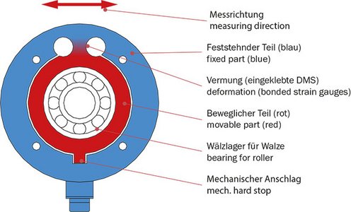
What is the difference between dead shaft and live rollers?
Dead shaft rollers are usually made of two separate parts. The non-rotating axis and the roller sleeve are connected via bearings. This allows the sleeve to rotate around the axis. In contrast, live shaft rollers are made from one piece. Bearings sit in each force sensor on either end of the roller. Dedicated types of force sensors are available for both types of rollers.
What is the nominal force of a force sensor / load cell?
The required nominal force FNom of a force sensor must be calculated individually per application. It determines the maximum force that a sensor can measure. Higher loads on the force sensors by web tension and the weight of the idler roller result in higher FNom. For applications where you use two force sensors on each end of an idler roller (typically for web tension measurement) the maximum load is divided by two, as the force is distributed evenly to the left and right. For FMS force sensors, the FNom is always specified in direction of the Red Point as this marking defines the measuring direction with positive sensor signal. The following information is essential for the calculation of FNom:
- entry and exit angle of the web (wrap angle) in relation to the horizontal ((to obtain a reference to the weight force)
- web tension (typically min. and max. values)
- weight of the idler roller.
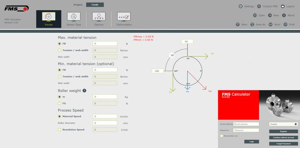
For easy and quick estimation of the required FNom, FMS offers a free online tool – the FMS Calculator
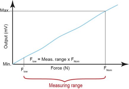
How does the nominal force affect the measuring range of a force sensor / load cell?
Many specifications of a force sensor refer to its nominal force FNom. This also applies to the measuring range. The measuring range is made up of the upper and lower values. The upper value is the nominal force, the lower value is calculated from the quotient of FNom. Typical specifications for the measuring range of FMS force sensors are 1:30 or 1:100. The following example shows the calculation of a LMGZ-series sensor with a FNom of 1´000 N. The measuring range always refers to the entire measuring range. In case of web tension measurement with two force sensors on an idler roller, the measuring range refers the mean value of both force sensors.
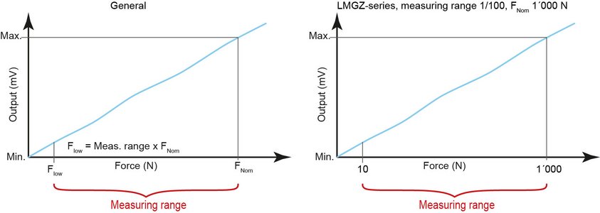
What is the measuring range of a force sensor?
FMS force sensors have three measuring ranges:
1:30 (x Fnom) – standard for most force sensors
1:100 (x Fnom) – LMGZ-series
1:500 (x Fnom) – LMGZD-series
FMS specifies the measuring range in relation to the nominal force. The force sensor can be used in the range between the nominal force (maximum force) and the minimum force. Above this range, it is overloaded; below this range, the accuracy no longer meets the specifications.
How does a force sensor work?
The main component of a force sensor is the measuring body. It is made of stainless steel or high-strength aluminum. It is designed so that it can deform by a precisely calculated amount at a specific point under a specific load. Strain gauges or strain gauges (DMS) are bonded to the metal at exactly this point. The strain gauges change their electrical resistance as a result of the deformation. This change is measured by the measuring amplifier and converted into a force value. Another component of a force sensor is the mechanical hard stop or overload protection to limit the deformation. It ensures that the measuring body is not damaged by the deformation.
How do I select the right force sensor?
When selecting a suitable force sensor, four criteria must be considered in parallel:
- Type of sensor
The type of applied idler rollers allows an initial selection of possible force sensors. FMS offers different designs to suit the respective roller type. Live or dead shaft rollers, rollers without shaft, for pillow block or as cantilever design are available. - Nominal force and size of the sensor
The physical properties of the web material, such as the maximum web tension and the web path around the measuring roller, determine the required nominal force. The weight of the idler roller also plays an important role here. - Application data
Special environmental parameters such as elevated temperatures, corrosive media, potentially explosive atmospheres, or other requirements can be taken into account by selecting the appropriate options. - Standard or customized solution
Force sensors from our standard range (force sensors overview) are generally our first choice. However, it is sometimes advantageous to be able to deviate from the standard quickly and uncomplicated in order to realize the optimal solution for your specific application.
We have compiled the complex selection process for you in a clear online tool: Link to the FMS Calculator
What is the accuracy class of an FMS force sensor / load cell?
FMS defines the accuracy as a function of the nominal force FNom of the respective force sensor and refer to this as the accuracy class. The accuracy class is made is made up of linearity error, hysteresis, and total error. All three influencing factors are verified during the final inspection of a force sensor before shipping. The accuracy class applies in the entire measuring range of the force sensor.
FMS-Calculator
What is FMS-Calculator?
FMS-Calculator is a browser-based program for sizing and selection of FMS force sensors.
Are there restrictions in the FMS-Calculator?
There are many factors you need to consider during the design phase. In addition to supposedly fixed specifications such as environmental influences and installation space, there are also other, often not yet defined boundary conditions that may change in the course of a project. To take these into account, we recommend that you discuss your designs with us. Our specialists can help you even if the application specifications may not lead to a clear result.
Which languages are supported by FMS-Calculator?
FMS-Calculator supports German and English. You can select the language as well as your preferred units in the settings.
Can I save calculations in the FMS-Calculator?
Yes, you can save any calculation. Create a project or add your calculation to an existing project and you can access it again at any time.
Can I exchange calculations with other users?
Projects and corresponding calculations can be shared with other Calculator users. On the project administration mask, you can add the email-address of the users you want to add to the project. Feel free to also add your FMS sales representative to get support with your calculation.
How can I size double-range force measuring of the LMGZD series?
Enter the maximum AND minimum material tension. Go to the Optimization step and select a dual-range force sensor of the LMGZD series. Select the size and nominal force and check in the force diagram (on theleft) whether the force sensor is suitable or not.
How are the results displayed in the FMS-Calculator?
After successful sizing completion, you can output the result as a file in a pdf format. The file is ideal for your internal documentation or further optimization.
What are the system requirements for the FMS-Calculator?
A computer with web browser and internet access.
Measuring Amplifiers
What are the advantages of ethernet communication over power outputs on a measuring amplifier?
The resolution of sensitive force sensors and amplifiers can be used much better using a 16 bit word instead an analogue signal (with a measuring range of 1:50 the signal is as small as 20 mV at lowest measurable point). Wiring of machines can be reduced a lot, and especially modular machines are much easier to connect from module to module.
What’s the difference between analogue and digital measuring amplifiers?
Analogue amplifiers use many more components that are temperature dependent, the worst being the potentiometers to adjust offset and gain. Signal filtering depends on capacitors that will lose their capacity over time. In digital amplifiers all parameters are stored reproducibly in a memory facilitating a replacement without recalibration.
FMS-segFORCE Segmented Tension Roller
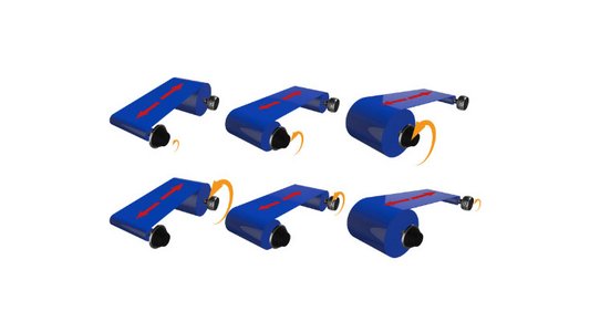
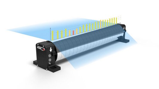
What is the FMS-segFORCE?
The FMS-segFORCE segmented tension roller is a new, advanced device designed to monitor web tension more accurately then conventional tension monitoring. It features multiple independent force sensors along the roller to provide detailed tension profiles.
What is the difference between conventional tension monitoring vs the FMS-segFORCE?
A roller with a set of standard loadcell can only measure the average tension across the width. Using a double-channel amplifier one can detect higher or lower tension on left or right side. With the FMS-segFORCE one gets a tension profile with up to 50 measuring points across the width of the web material. The resolution of the profile can be set by selecting appropriate segment width and quantity.
Where is the FMS-segFORCE applied?
One main application is in the quality control of web material. The tension profile can be used to identify defective material and exclude it from further processing steps. The causes can be determined and corrected before valuable machine hours are lost. The tension of the individual slit strips can also be measured in secondary slitter / rewinders. Deviations are directly indicated, and suitable countermeasures can be taken.
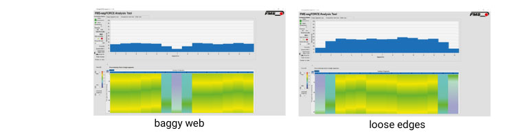
What kind of defects or properties can an FMS-segFORCE detect?
The FMS-segFORCE has been applied in a wide range of applications and industries. From film extrusion, coating to slitting, from battery foils to sandpaper production. The following list is only an excerpt of possibilities.
- Loose edges
- Baggy web
- Single-sided tension
- Not properly aligned idler rollers
- Uneven coating thickness
- Defective differential shafts
- Out of round parent roll
- Gauge deviations
What is a tension profile created with the FMS-segFORCE?
The FMS-segFORCE is a tension measuring roller with up to 50 independent force sensors across the entire roller. The sensors can be placed directly next to each other. Each of them generates a tension reading for the respective part of the web. If you take all these values together and arrange them according to time, you obtain a tensile profile. A tensile profile can be used to make direct statements about the quality of the web. Defects such as loose edges or droopy web are easy to recognize.
Can the FMS-segFORCE cut down costs?
Yes, the FMS-segFORCE can help you to detect scrap production in a very early stage. Before you waste valuable operator and machining hours, the FMS-segFORCE detects faulty material and allows you the react in time. Change material, safe time and costs.
Web Guiding Solutions
What is a web guide?
Web guides are typically used where web type material is processes from roll-to-roll. These devices control the lateral alignment of the web. Any misalignment is detected with material sensors and directly leads to a correction by the actuator. In general, three components are required for all types of web guides:
- Material sensor – Depending on the web material, ultrasonic or optical sensors are used to detect the edge of the web. This signal with the actual position of the web is then sent to the
- Web guiding controller – Controls the closed-loop functionality of the entire system. It comes with display and operating options. If the deviation between the actual and reference values is too high, the controller will send a signal to the actuator to correct the position of the web immediately.
- Actuator - Mechanical assembly that "moves" the material web sideways. Due to the different installation situations, there are many types of actuators.
The different types of web guiding systems are also named according to the type and characteristics of the actuators. Here are the two most important ones:
Linear actuators – Used at the beginning or the end of machines. An unwinding station holds the parent roll and feeds the web into the process. To adjust the alignment of the web, a linear actuator is used to push the entire (unwinding) assembly back an forth.
Steering frame – Used for intermediate web guiding inside the machine, mainly prior to an important process step. The web path with four times 90° wrap angle of the material is typical for steering frame web guides. This avoids shear stress on the material web.
What is the web handling principal or normal entry rule?
If a web is in traction with a roller (idler or driven) it seeks to align itself perpendicular to the roller. That means that in a complex machine with many rollers, the precise parallel alignment of the rollers is essential for its functionality. Nevertheless, the web guiding system can rarely be avoided.
Telemetry Systems
What are telemetry systems?
Many types of stranding machines are used in the wire & cable industry. The special design often does not allow the use of cables for the transmission of signals and measurement data. Instead, systems that use radio for data transmission are used. FMS has multiple systems in this industry. Over the last few decades, FMS has developed several such systems for different types of machines and applications. All of them use wireless signal transmission and are summarized under the umbrella term telemetry systems.
What is the RTM X42 Telemetry System?
It is a retrofittable system for strand tension monitoring and tension control in stranding machines. Up to 42 force sensors on the layplate, shortly upstream the stranding point, measure the tension of all individual strands. The readings are transmitted wirelessly to the operator’s station and displayed graphically.
- Objective tension reading support the operators
- Helps to get equal tension on all strands
- Increased product quality
For further automation of your production the systems can be extended to a full closed-loop tension control system. Friction type brakes can be equipped with brake actuators on each cradle. They automatically readjust the brake tension of each spool depending on the preset reference tension of the respective strand.
- Uninterrupted production, w/o downtimes for manual readjustment of brakes
- Absolute safe and repeatable processes für further relief of operators