Tension measurement of individual web sections
In slitting, the tension measurement of individual webs has so far mainly found its way into primary slitters / rewinders. On machines of this size, there is sufficient space for several individual measuring rollers. In the case of more compact machines (up to two meters working width), the focus is on using winding and differential shafts to keep the material tension of all parallel web sections as uniform as possible. With this method, however, the individual material tensions remain unknown and can vary greatly. FMS offers a novel concept with the FMS-segFORCE®. A measuring roller with several independent force sensors for tension measurements in each individual web section.
Quickly detecting the smallest of deviations and eliminating their cause
If we imagine the ideal process, the slitting process would run reliably for weeks and months under the same conditions and produce consistently high quality. However, the reality looks very different. Significant deviations in the consistency and properties of the individual parent rolls can lead to issues from the start. These are, for example, discrepancies in material thickness, elasticity, winding quality, or different environmental influences on the parent roll. In addition, there are system-specific influences such as component wear and thermal influences and the resulting irregularities in the manufacturing process. The causes mentioned and their effects are not always easy to identify and eliminate. With the new solution, manufacturers and machine builders in the converting industry now have the option of precisely measuring the web tension of individual cut strips. Especially with very thin and elastic materials and in compact systems, this task places the highest demands on the technology used.
Discontinuous material properties and varying process parameters
Even minor fluctuations in material quality and process parameters can harm the winding quality. In this way, typical defect patterns such as telescoping or dishing rolls due to loose windings or damaged rolls due to excessively tight windings on individual webs or entire wound-rolls can be avoided. The condition of the differential shafts is also crucial for a consistently high winding quality. Many mechanical parameters, such as friction coefficients, optimal function of the friction rings, condition of the roller bearings, etc., must be ideally matched but cannot be monitored directly. However, common contaminations from dust, etc., have a negative influence here. Thus, constant quality requirements will no longer be met after a while. Creeping defect patterns in production are not detected. The tension measurement of individual material panels helps to identify differences between cut strips in time. With the FMS-segFORCE measuring roller, such defects can be detected as they occur in real time. The material tension on each individual panel is measured, and the ongoing process can be better controlled and optimized. Production waste is reduced, and complaints are avoided. No more defective batches are delivered to customers.
Measuring roller design
The FMS-segFORCE measuring roller consists of a dead shaft on which the individual movable segments are arranged. The segments are securely locked in place pneumatically via a central connection in one of the two side brackets. The segments themselves contain the actual non-rotating force sensor, a compact measuring amplifier, and the bearing in the roller shell. The segments are supplied with power, and signals are routed wirelessly via the central shaft. A well-protected, automatic connection of the electrical contacts simplifies the force sensors’ quick axial positioning for the respective application. Not a single cable needs to be disconnected or reconnected for such repositioning. The measuring roller is connected to the machine frame on both sides via functional side brackets similar to pillow blocks. One of these also contains parts of the electronics. Well protected from dirt and environmental influences. The 24 VDC power supply and the required compressed air connection are connected to one of the housings. An RJ45 socket is available for data transfer. The signals can be picked up and either visualized via a PC or forwarded to the PLC. The number, width, and axial position of the individual segments can be individually adapted to the machine and the process requirements. Broad coverage of different material and slitting widths can be easily achieved by correctly assigning segment widths and spacings.
Display and data analysis
FMS offers two different data management solutions. The PROFINET protocol provides a universally applicable Ethernet interface. It can be used to transmit all measured data in real time to the PLC. Thus, the machine control can be used for displaying actual values and outputting warnings or fault states in a fully integrated manner. In addition, a separate FMS software offers convenient operation and configuration options via a standard PC. The force sensors and the display can be configured via the FMS software. A well-arranged display informs the operator at any time about the status of the measuring system.
Image gallery
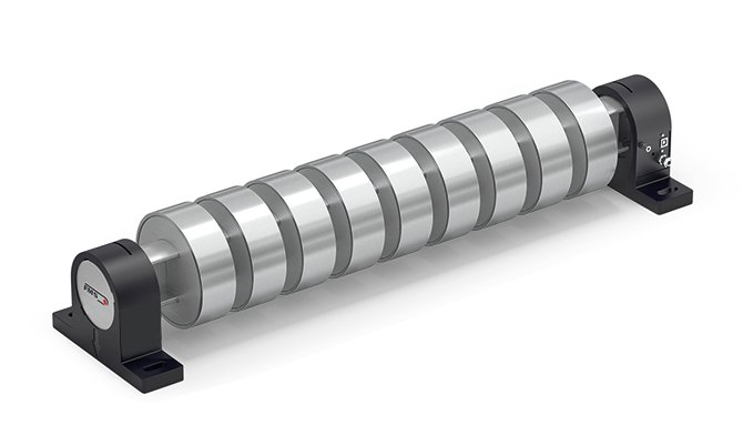
The individual segments can be seen clearly on the shaft. Each individual segment contains a fully-fledged force sensor, which is evaluated individually.
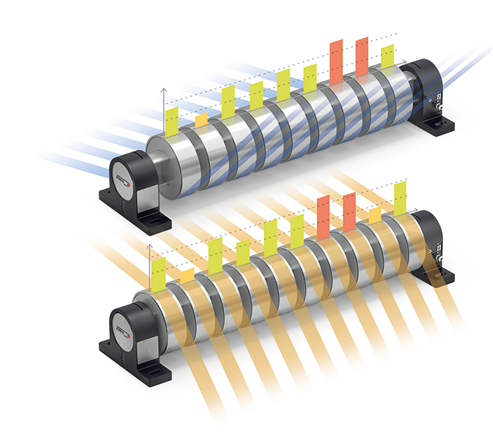
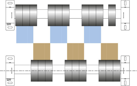
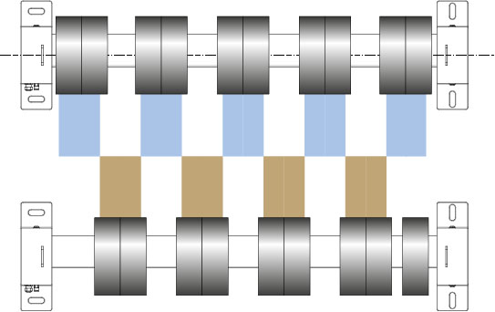
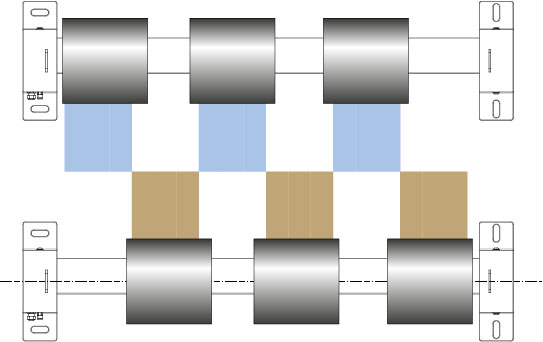
Schematic of two measuring rollers in the slitter winder. The offset of the individual segments from one measuring roller to the other can be clearly seen. Minimal differences in tension between the individual webs become visible quickly. The sophisticated design allows all types of wrap angles to be covered. Flexible segment widths and freely adjustable spacings between the segments allow the measuring roller configuration for a wide variety of slitting widths.
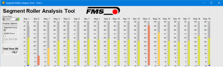
Display of the individual tension values per segment. The deviating values of channels 2 and 13 are clearly visible. Unusual tension values indicate, for example, wear or increased temperature of individual friction elements. These are, for example, caused by contaminations.
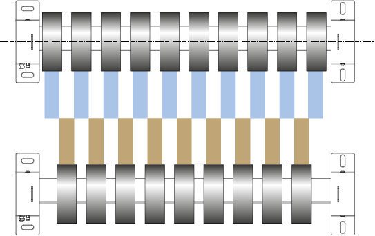
Cut 1: 1 segment per cut
Cut 3: 3 segments per cut
Cut 2: 2 segments per cut
Cut 4: wider segments
The illustrations show examples of the adjustment options between slitting width and segment width. In each case, a different number of strips is cut from the same parent roll. The number and width of the segments that can be used best and most efficiently are also determined by the desired slitting widths.